Development of an Intelligent Onboard Avionics Software Platform for Emergency Detection and Response in Urban Air Mobility (UAM) – Research
1. Research Overview
This research aims to develop an intelligent, onboard avionics software platform for Urban Air Mobility (UAM) vehicles that can autonomously detect, assess, and respond to abnormal or emergency flight conditions. The system is being designed in compliance with the FACE (Future Airborne Capability Environment) standard, enabling high modularity, portability, and safety. Development is currently ongoing in its second year, with architectural design completed and progressive implementation underway.
Research Duration: April 2024 – December 2027
Lead Organization: VSPACE
Participating Organizations: DAVICH TRANS, Lihigh, Hanwha Systems, KETI, Korea National University of Transportation
Role: Principal Development Organization
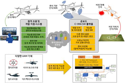
Figure 1. Overall UAM emergency response framework, showing the linkage between the remote control system, onboard C-IMA software, and fault-aware landing scenarios.
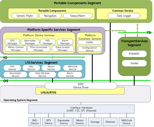
Figure 2. FACE-compliant architecture diagram, visualizing modular segmentation from OS to portable components, ensuring safety and reusability.
2. Research Motivation
In the rapidly evolving UAM industry, operational safety is one of the most critical challenges, especially during abnormal conditions such as motor failures, sensor malfunctions, or communication loss. While traditional aircraft rely on manual pilot responses or remote monitoring, UAM vehicles often require fully autonomous or semi-autonomous response capabilities. The motivation for this research stems from the need to embed real-time emergency detection and mitigation logic directly within the aircraft. This is essential not only for fail-operational capability but also for future airworthiness certification.
3. Technical Objectives
- Research and design a FACE-compliant avionics software architecture optimized for UAM platforms
- Implement real-time monitoring of flight-critical sensors and actuators
- Develop fault detection and classification algorithms for abnormal flight events
- Integrate emergency decision-making logic
- Research and validate the platform using SIL and HIL simulations
- Research and prepare the system for actual UAM aircraft integration
4. My Contributions
I am currently leading the system-level design and technical direction of this national R&D project. My responsibilities include defining safety and functional requirements, overseeing the modular FACE-based architecture, managing subsystem integration, and coordinating industry and research partners to prepare for real vehicle testing.
5. Engineering Approach
The system is engineered around the FACE (Future Airborne Capability Environment) architecture, which enables modular software development with defined communication and data exchange standards. The software stack is divided into segments: Portable Components (PCS), Platform-Specific Services (PSSS), Transport Services (TSS), I/O Services, and Operating System abstraction layers. Each emergency scenario—ranging from partial motor loss to full sensor blackout—is associated with state-transition logic and corresponding fallback actions.
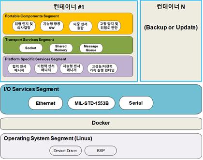
Figure 3. FACE container-based architecture showing Dockerized deployment across redundant containers for modular fault isolation and recovery logic.
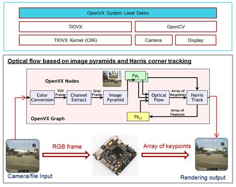
Figure 4. Vision-based fault recognition test using optical flow and keypoint tracking, used in our navigation fallback module under sensor failure.
6. Validation and Testing – Extended Dataset
Validation is being carried out using a combination of Software-in-the-Loop (SIL) and Hardware-in-the-Loop (HIL) setups. Emergency scenarios including GPS spoofing, battery over-discharge, rotor malfunction, and complete loss of communications are triggered through a custom-developed fault injection interface. The system’s response is measured by evaluating metrics such as reaction time, decision latency, and recovery trajectory success.
Real-time telemetry, system logs, and motor behavior are continuously recorded. Additionally, benchmark tests using inertial-only navigation and mission rerouting are used to verify fallback logic robustness. We also monitor system bus traffic, partition isolation performance, and watchdog mechanisms under prolonged operation.
7. Research Outcomes
- Research outcome: development of a modular, FACE-standard compliant avionics software platform tailored to emergency response needs
- Research outcome: construction of a complete SIL/HIL validation bench with repeatable emergency scenario injection
- Research outcome: deployment of core detection modules into a multicopter hardware testbed under simulated rotor failure
- Research outcome: published interface specifications for multi-partition architecture to ensure long-term scalability and certification readiness
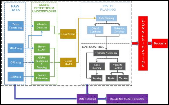
Figure 5. System-level perception and planning architecture used for context-aware emergency response decisions including trajectory replanning.
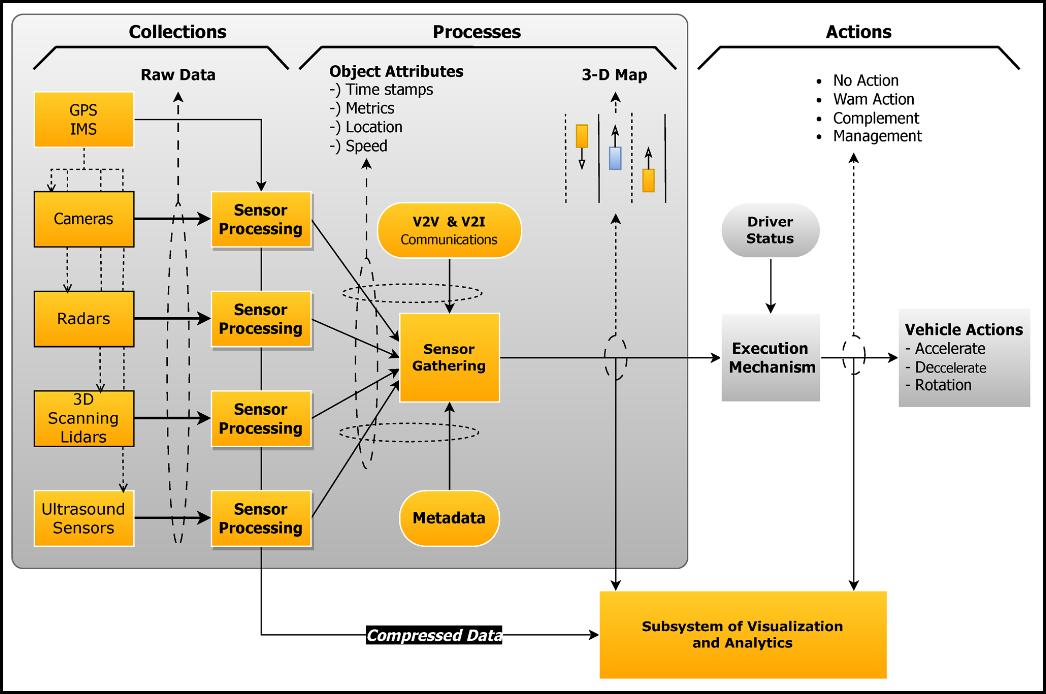
Figure 6. Execution stack diagram for embedded decision engines, integrating V2X, radar, and inertial navigation sources for robust recovery logic.
8. expectation effectiveness
- The platform is currently undergoing integration with a custom-built UAM prototype based on a single-seat multicopter configuration, with plans to expand into a three-seat variant in the near future.
- Software modules are deployed in a redundant computing container environment. Each container includes navigation, sensor fusion, emergency handling, and interface modules. The system is also being evaluated for conformance to DO-178C and FACE validation suites. We anticipate that the platform will be capable of self-contained emergency response—including autonomous diversion and forced landing—in uncontrolled flight conditions.
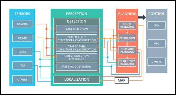
Figure 7. Full autonomy stack integrating perception, planning, and control modules, aligned with our modular avionics interface structure
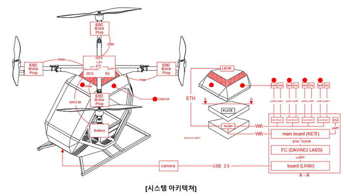
Figure 7-1. System explain.
8. Test - ing
Integration & Testing Phase
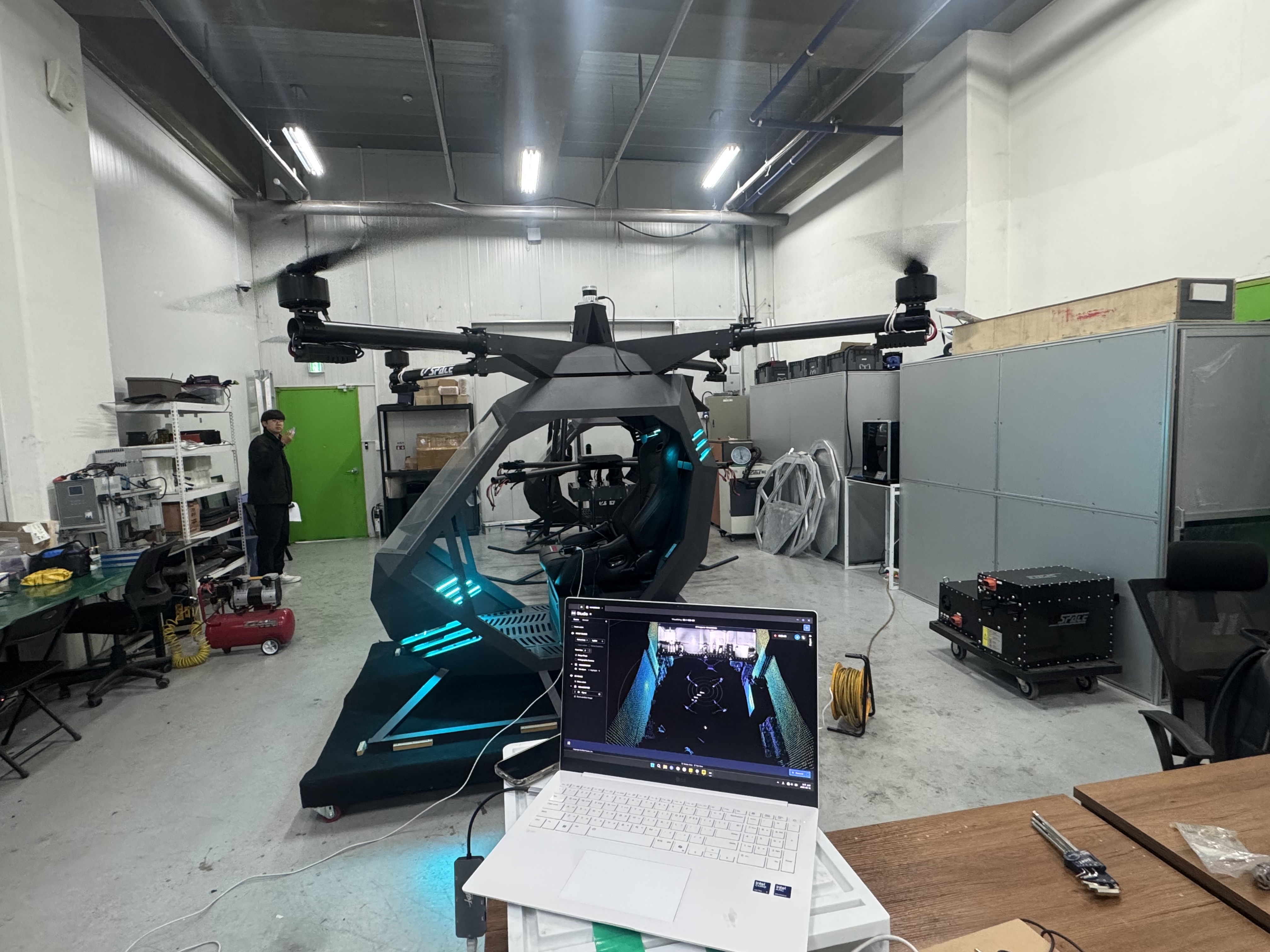
Figure 9. Lidar Testing 2.
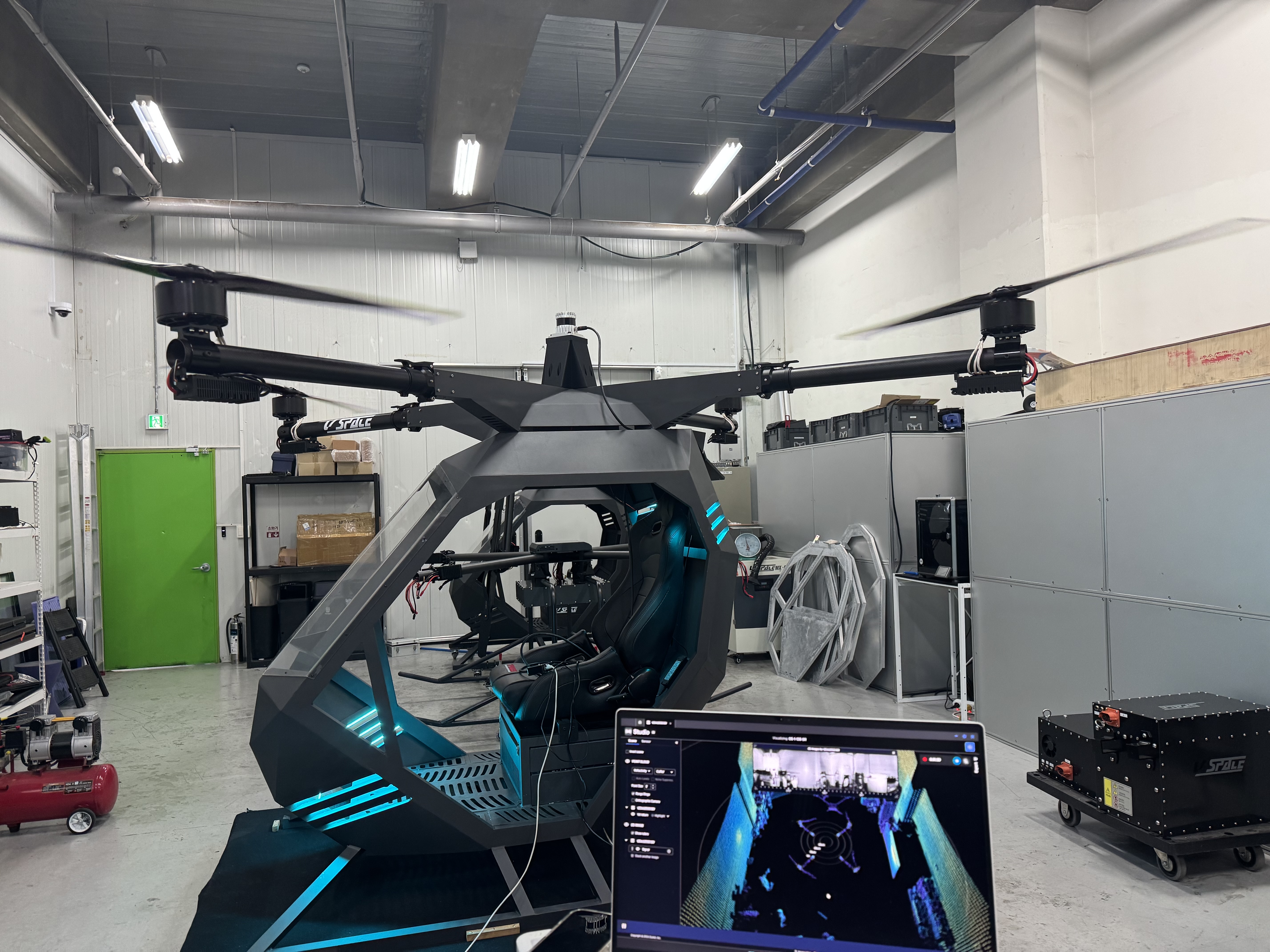
Figure 8. Lidar Testing 1 .