Development of a High‑Efficiency, Low‑Emission Multi‑Channel Electric Drive PTO Power Module for Commercial Special‑Purpose Vehicles
1. Research Overview
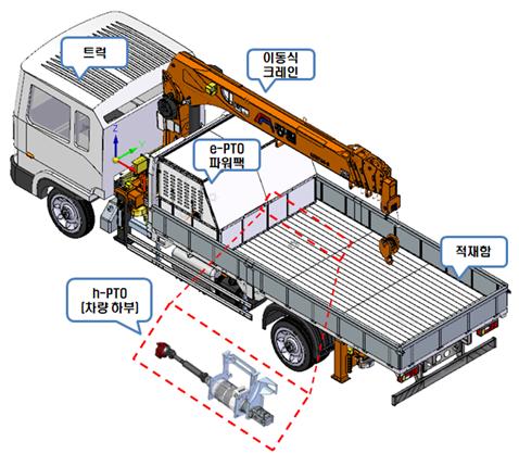
This project, led by Kwanglim Co., Ltd., aimed to develop a multi-channel electric Power Take-Off (e-PTO) system applicable to commercial special-purpose vehicles such as dump trucks and cranes. Traditional PTO systems mechanically link internal combustion engines to drive hydraulic equipment, leading to fuel consumption and emissions even when idling. This project sought to eliminate those inefficiencies and environmental issues by adopting a high-voltage electric power system.
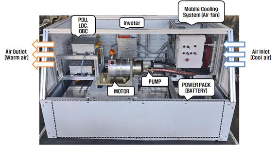
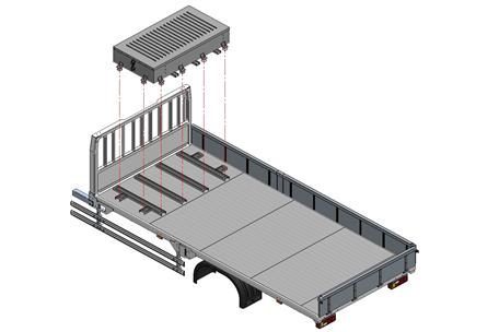
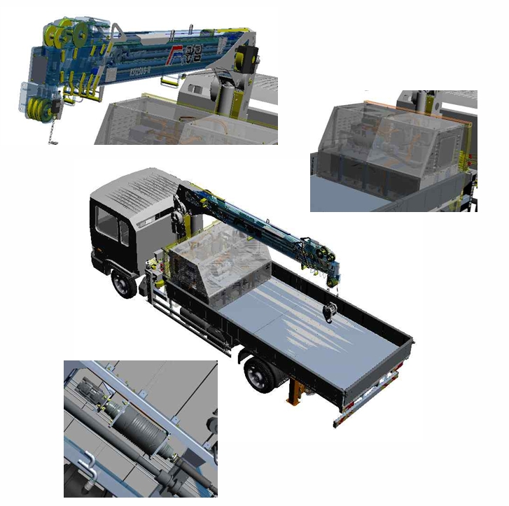
The e-PTO system integrates a high-power battery pack, inverter, power distribution unit (PDU), and vehicle control unit (VCU) into a single housing called the e-Powerpack. VSPACE Co., Ltd. was responsible for the battery module and BMS development, covering mechanical design, thermal structure, BMS firmware, and communication interface.
The final output of this project was a mass-production-ready e-PTO system with three-channel output, achieving safety, durability, and energy efficiency benchmarks for electric special-purpose vehicles.
Project Details
- Project Title: Development of High-Efficiency, Low-Emission Multi-Channel Electric Power Take-Off System for Commercial Special-Purpose Vehicles
- Program: Commercial Vehicle Innovation & Future Industry Ecosystem Program (Ministry of Trade, Industry and Energy, Korea)
- Duration: April 2020 – December 2022
- Lead Organization: Kwanglim Co., Ltd.
- Participating Organizations:
- VSPACE Co., Ltd. (Battery module design and BMS development)
- Global Engineering Co., Ltd. (Motor design and fabrication)
- KAI Tech (Power control unit testing and production evaluation)
- Korea Automotive Technology Institute (Cooling system analysis and optimization)
- Korea Electronics Technology Institute (Control software and functional safety verification)
- Project Director: Mr. Kim Ok-Geun (Kwanglim Co., Ltd.)
- Battery System Lead: Mr. Suho Yu (Director, VSPACE Co., Ltd.)
2. Research Motivation
Conventional PTO systems operate by drawing mechanical power directly from the engine, resulting in constant fuel consumption and emissions even when the vehicle is stationary. In light of stricter emission regulations and rising fuel prices, a cleaner and more efficient power system became essential for the future of commercial special-purpose vehicles.
Moreover, the increasing demand for electrification of commercial utility vehicles has created an urgent need for a robust, modular electric PTO system. Unlike passenger EVs, these platforms require intermittent high‑power output, thermal resilience, and fault‑tolerant architecture—challenges that are unique and cannot be easily addressed by off‑the‑shelf EV components.
3. Technical Objectives
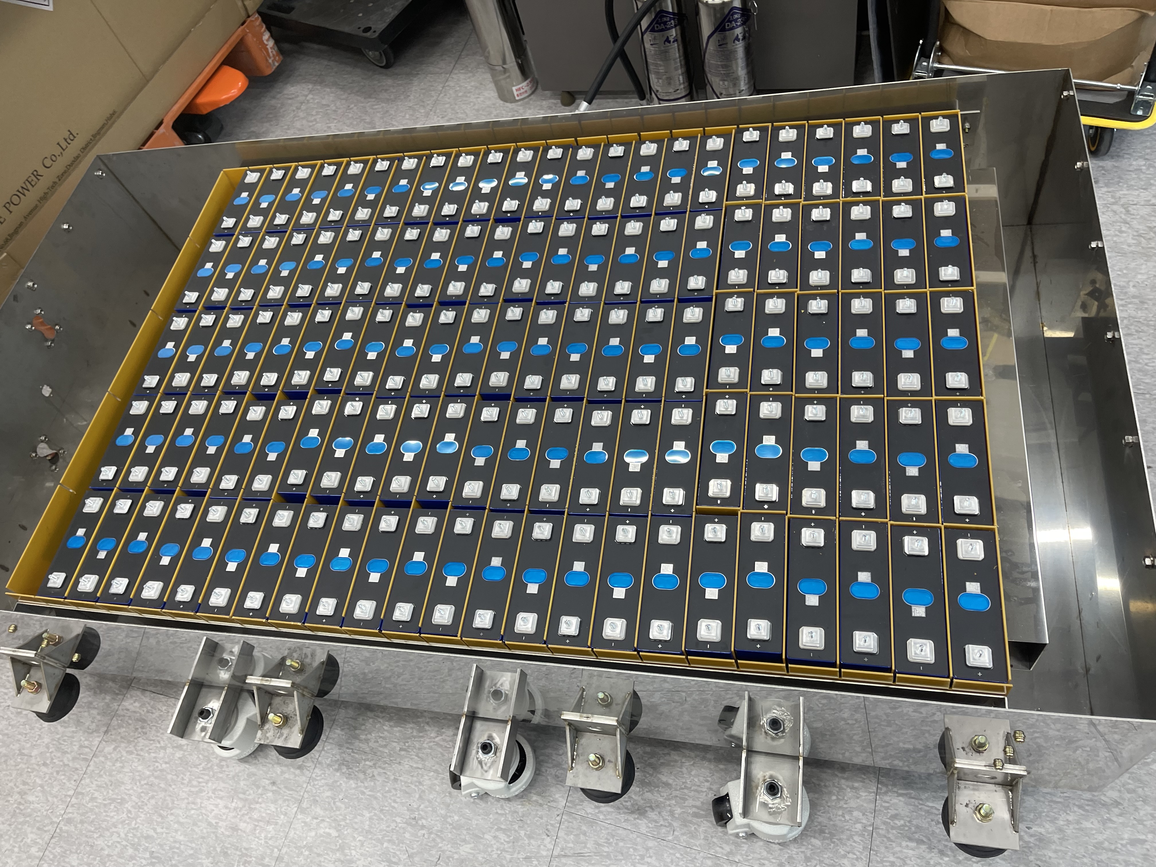
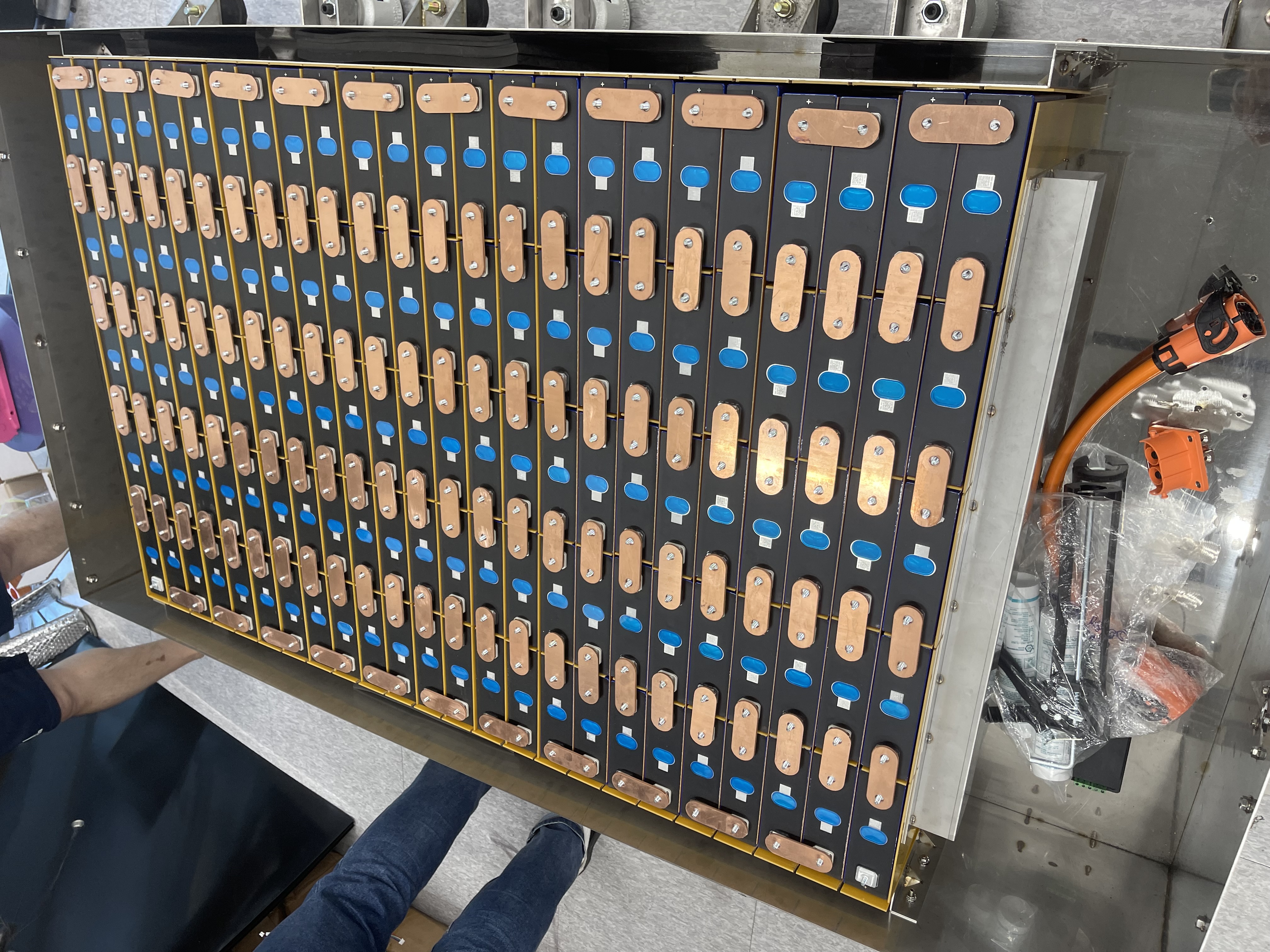
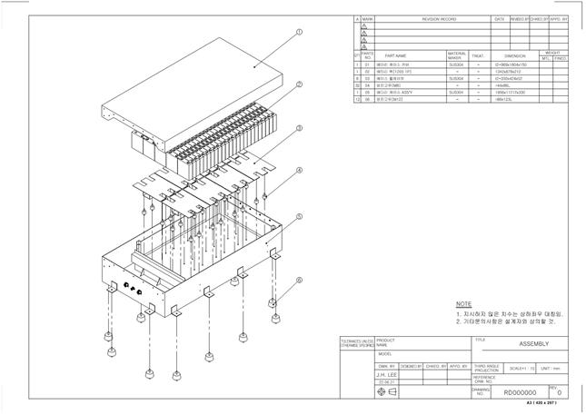
- Design and validate a modular 123S1P battery pack using 3.2 V 200 Ah prismatic LFP cells
- Ensure compatibility with a three-channel e-PTO motor system capable of high transient current output
- Achieve thermal stability using a passive aluminum conduction path without active cooling mechanisms
- Implement a CAN-based BMS for real-time monitoring of voltage, temperature, and current
- Validate safety mechanisms including over-voltage, under-voltage, over-temperature, and short-circuit protection
- Demonstrate mechanical vibration tolerance and on-vehicle electrical performance under working loads
4. My Contributions
As the Battery System Lead at VSPACE Co., Ltd., I oversaw the end-to-end development and integration of the high-voltage battery system for the e-PTO application. My responsibilities covered both hardware and firmware domains, spanning component selection, 3D mechanical design, thermal safety architecture, and system-level validation.
- Selected and verified 3.2 V 200 Ah prismatic LFP cells based on IR and capacity tests
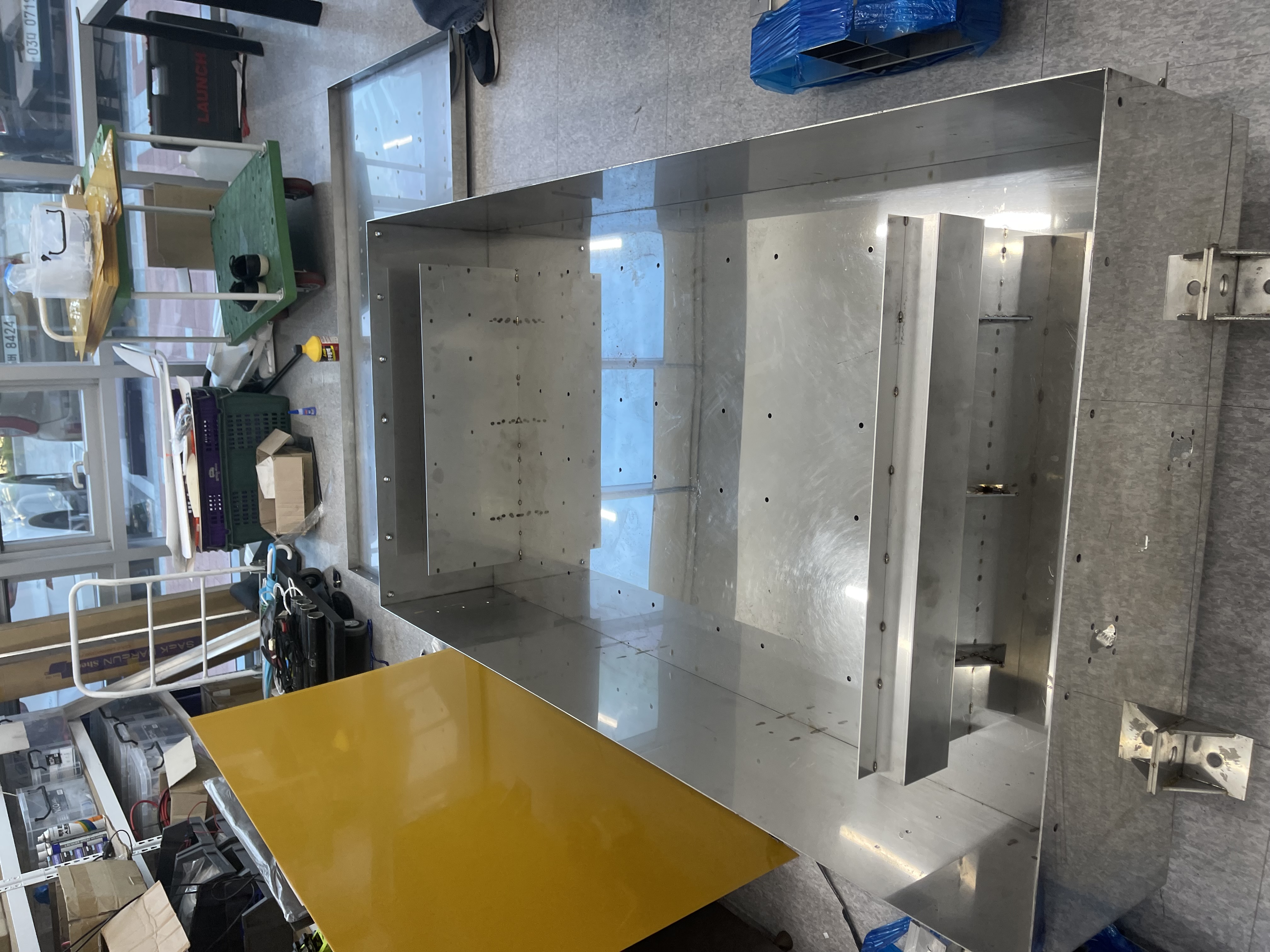
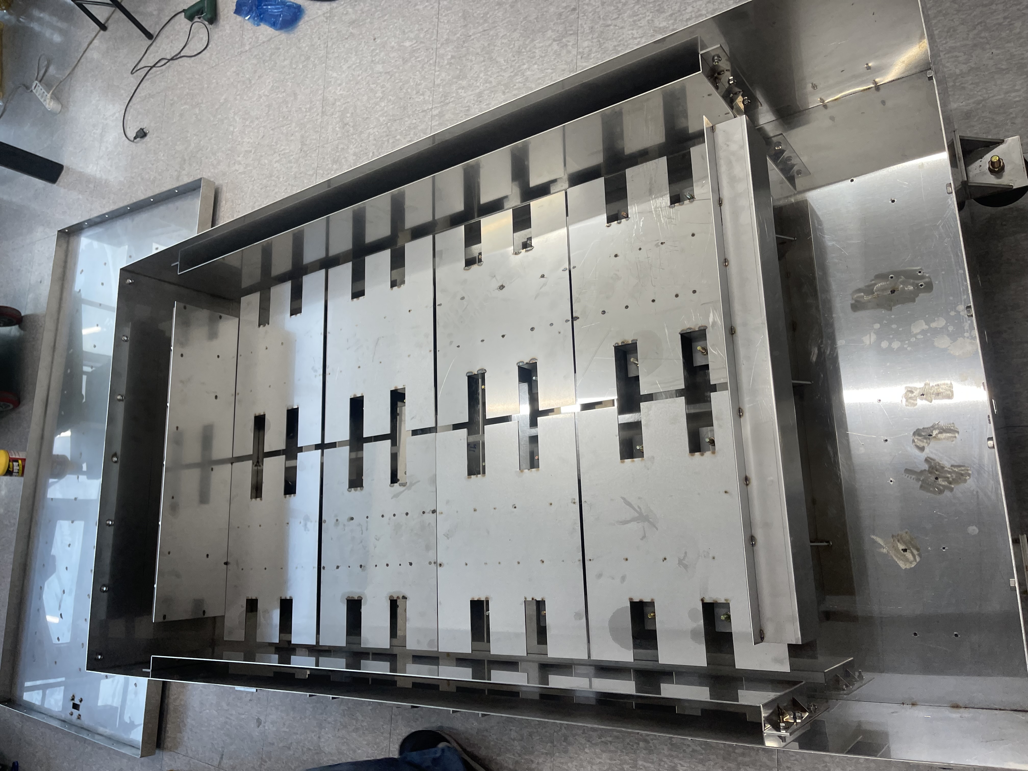
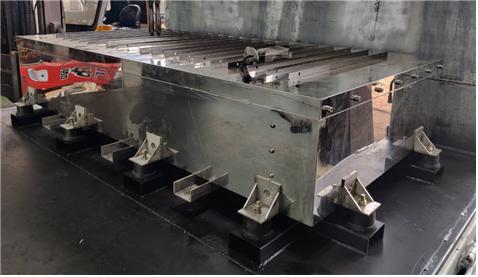
- Designed the 123S1P module architecture and aluminum enclosure to meet thermal and structural safety requirements
- Developed the BMS interface for CAN communication with inverter and vehicle controller (VCU)
- Led mechanical CAD modeling for vehicle integration, including mounting points and cooling interfaces
- Conducted final on-vehicle validation for vibration durability, thermal behavior, and electrical control handshake
5. Engineering Approach
The design began with load estimation and thermal analysis of the PTO system under real operation cycles. To minimize thermal runaway risk and eliminate the need for active cooling, we implemented an aluminum frame structure that conducted heat away from the core.
The battery housing was constructed to IP67 standards, with foam supports and cell holders absorbing vibration from the chassis. We used rubber-padded aluminum endplates and laser-welded busbars to ensure high current reliability.
CAD modeling ensured compatibility with vehicle mounting points and clearance for electrical harnesses. The final battery pack design was simulated and validated through structural FEA and thermal CFD models before fabrication.
6. Validation and Testing – Extended Dataset
The 123S1P battery pack underwent a full series of tests to verify its performance under real-world conditions. First, pre-assembly cell screening was conducted for internal resistance and capacity deviation. Only matched cells were accepted into final module assembly.
After mechanical assembly, the pack was instrumented with temperature sensors and current shunts for lab testing. Tests included high-current discharge cycles, thermal rise monitoring, vibration endurance, and insulation resistance checks.
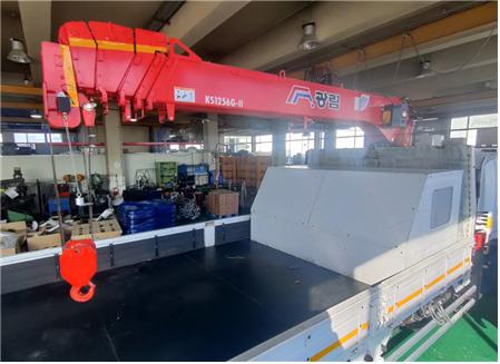
Finally, the battery pack was mounted on the test vehicle and connected to the e-PTO system. Field validation included thermal soak runs, load cycling under working hydraulics, and CAN communication monitoring between the BMS and inverter.

7. Research Outcomes
The developed e-PTO battery system met all target requirements for power output, durability, and vehicle-level integration. The 123S1P pack architecture proved stable across repeated high-current cycles, with minimal temperature rise and no cell imbalance over time.
The BMS communicated seamlessly with the inverter and vehicle controller, and all CAN nodes responded within latency specifications. The mechanical enclosure survived >10 hours of vibration testing and real-road operation without structural or thermal failure.
All modules were designed for mass production readiness, with manufacturable busbar layouts, laser-welded connections, and water/dust ingress protection.
8. Applied Product
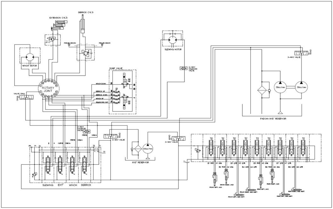
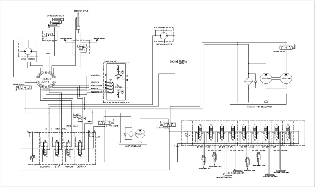
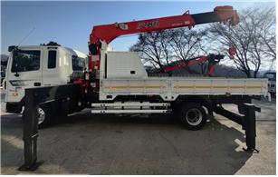
The battery system developed through this research has been fully integrated into an electric Power Take-Off (e-PTO) system for commercial special-purpose vehicles. It powers hydraulic cranes, tippers, and auxiliary devices without idling the engine, drastically improving fuel economy and reducing emissions.
Two configurations were tested: one for driving-only e-PTO and another for driving + generation (H-PTO). The system has been successfully operated in real vehicles with active hydraulic loads.
The design allows for modular adaptation across various truck platforms with different voltage, capacity, and mounting configurations. This e-PTO system marks a practical transition step toward fully electrified utility fleets.