Urban Air Mobility (UAM) Type Certification Research (Task 3-1-2)
1. Research Overview
This national research (3-1-2) aims to establish Korea’s first Type Certification (TC) for electric vertical takeoff and landing (eVTOL) aircraft. Rather than designing a new airframe from scratch, this research focuses on modifying an existing aircraft into a compliant Lift & Cruise-type platform. The work is being conducted in collaboration with the Korea Institute of Aviation Safety Technology (KIAST) to validate system performance and co-develop a Korean eVTOL certification framework.
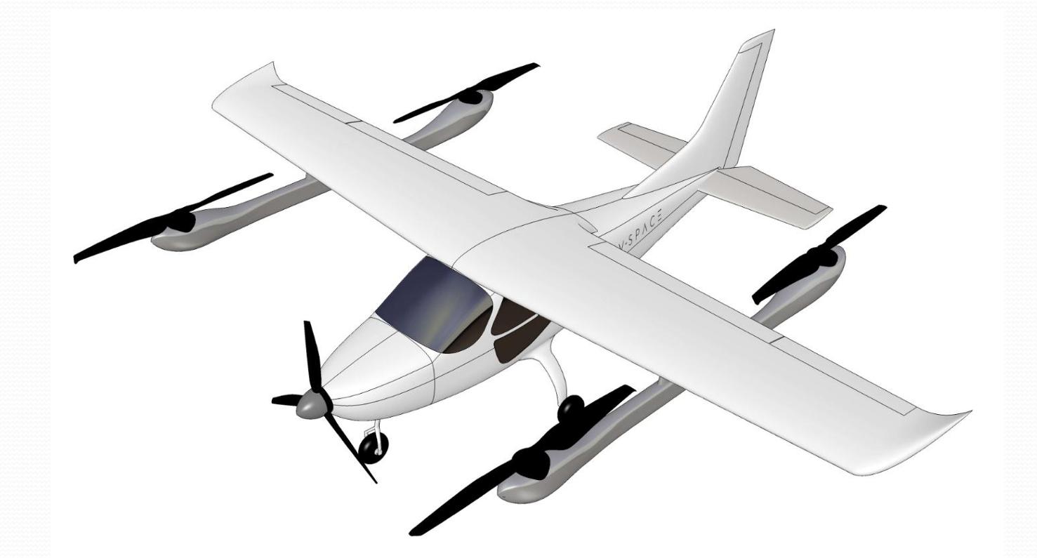
Figure 1. UAM TC candidate aircraft 3D CAD model.
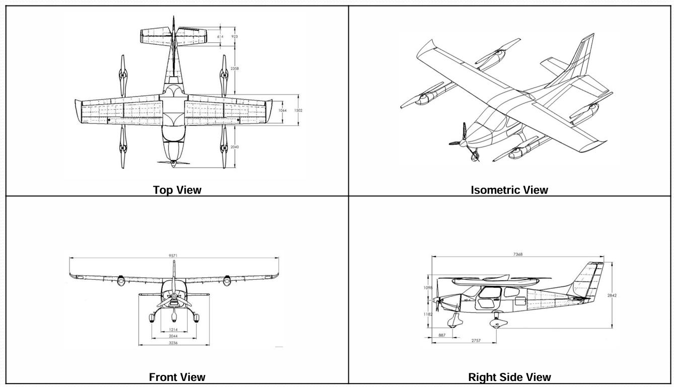
Figure 2. Airframe blueprint drawing for TC application.
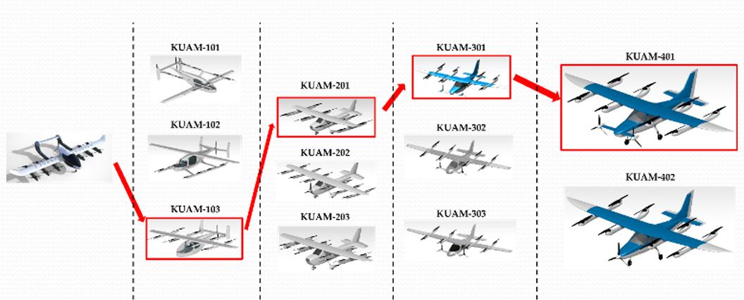
Figure 3. Outer Mold Line (OML) evolution during structural iteration.
2. Research Motivation
eVTOL aircraft introduce unprecedented technical features, such as distributed electric propulsion (DEP), high-voltage battery systems, and full digital flight control. These innovations exceed the boundaries of existing airworthiness frameworks. This research addresses the global certification gap by developing Korea’s own regulatory pathway through real-world aircraft integration and validation.
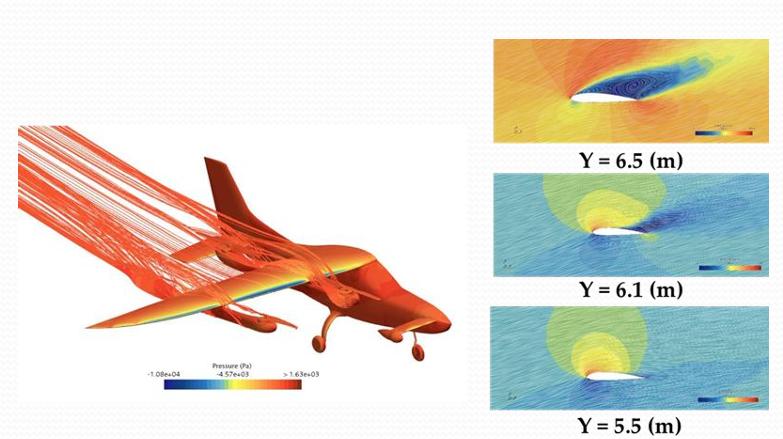
Figure 4. CFD analysis at AOA 14° showing lift distribution.
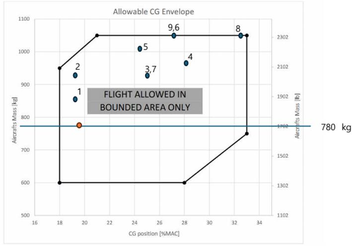
Figure 5. Weight and CG distribution strategy for Lift & Cruise configuration.
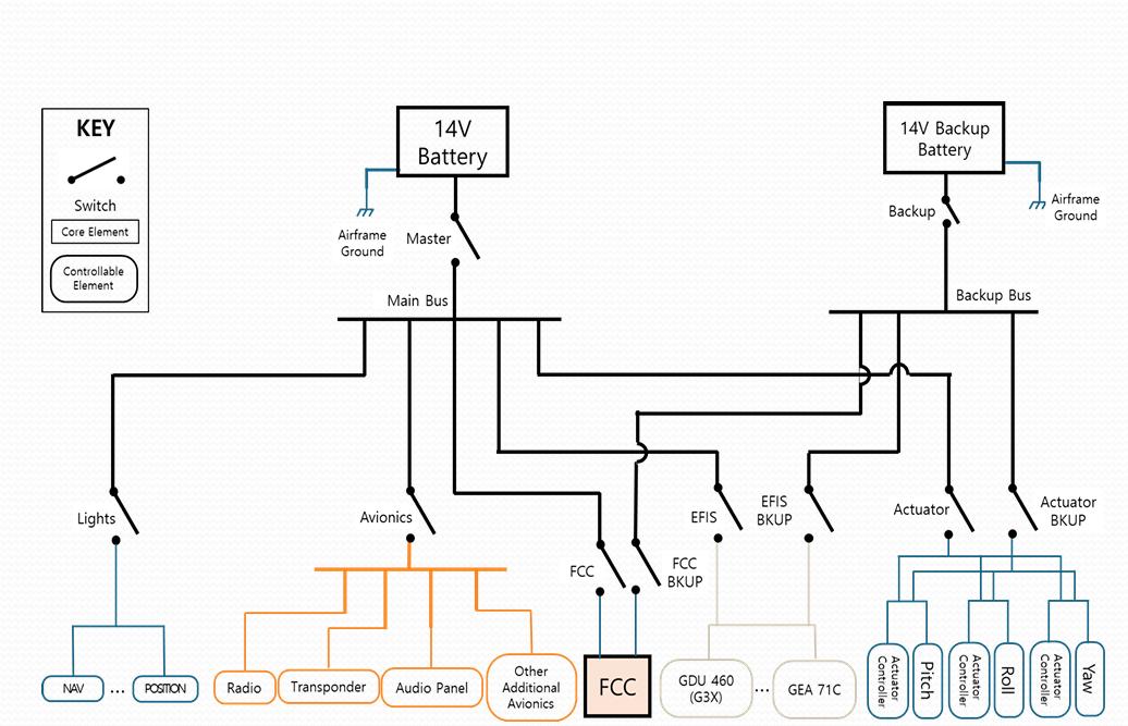
Figure 6. Low-voltage electrical system configuration.
3. Technical Objectives
- Modify an existing aircraft into a Lift & Cruise configuration
- Develop TC-compliant power, control, and energy systems
- Define fail-operational logic and fault-tolerant architectures
- Generate data-driven safety documents and traceability maps
- Prepare the aircraft for compliance testing and flight trials
- Contribute empirical data for shaping eVTOL certification standards
4. My Contributions
As a systems engineer and participating researcher, I contributed to:
- High-voltage battery system design and integration
- Low-voltage electrical distribution architecture
- Distributed propulsion architecture for redundancy
- Control system layout and FCC/BMS integration
- Certification planning and CG compliance strategy
- Technical coordination with KIAST on requirement flow
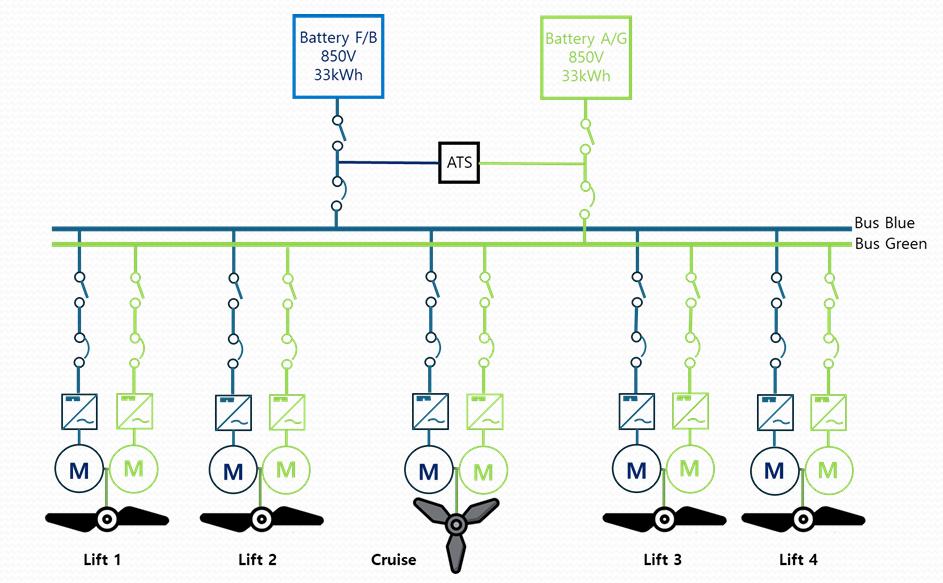
Figure 7. Distributed electric propulsion system overview.
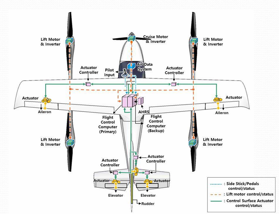
Figure 8. Flight control computer (FCC) layout and redundancy setup.
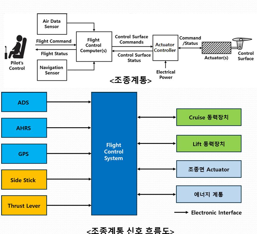
Figure 9. Signal flow and powerline routing diagram.
5. Engineering Approach
The aircraft employs dual power buses, modular batteries, and a redundant FCC control system. Subsystem integration was validated against CG constraints and flight control logic was structured with failover paths. Wiring harness, EMC shielding, and signal routing were engineered based on system-level certification logic.
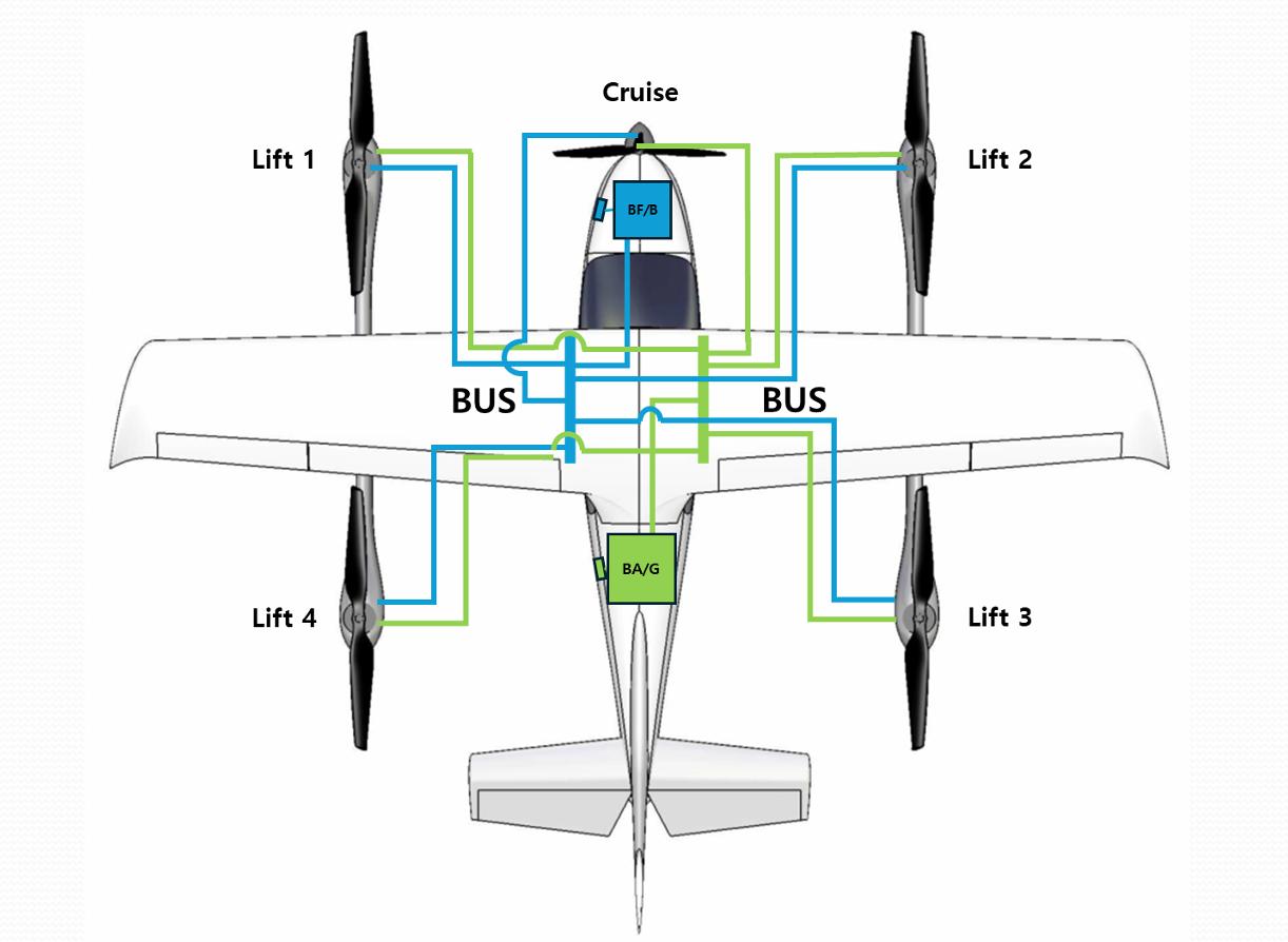
Figure 10. High-voltage energy system schematic.
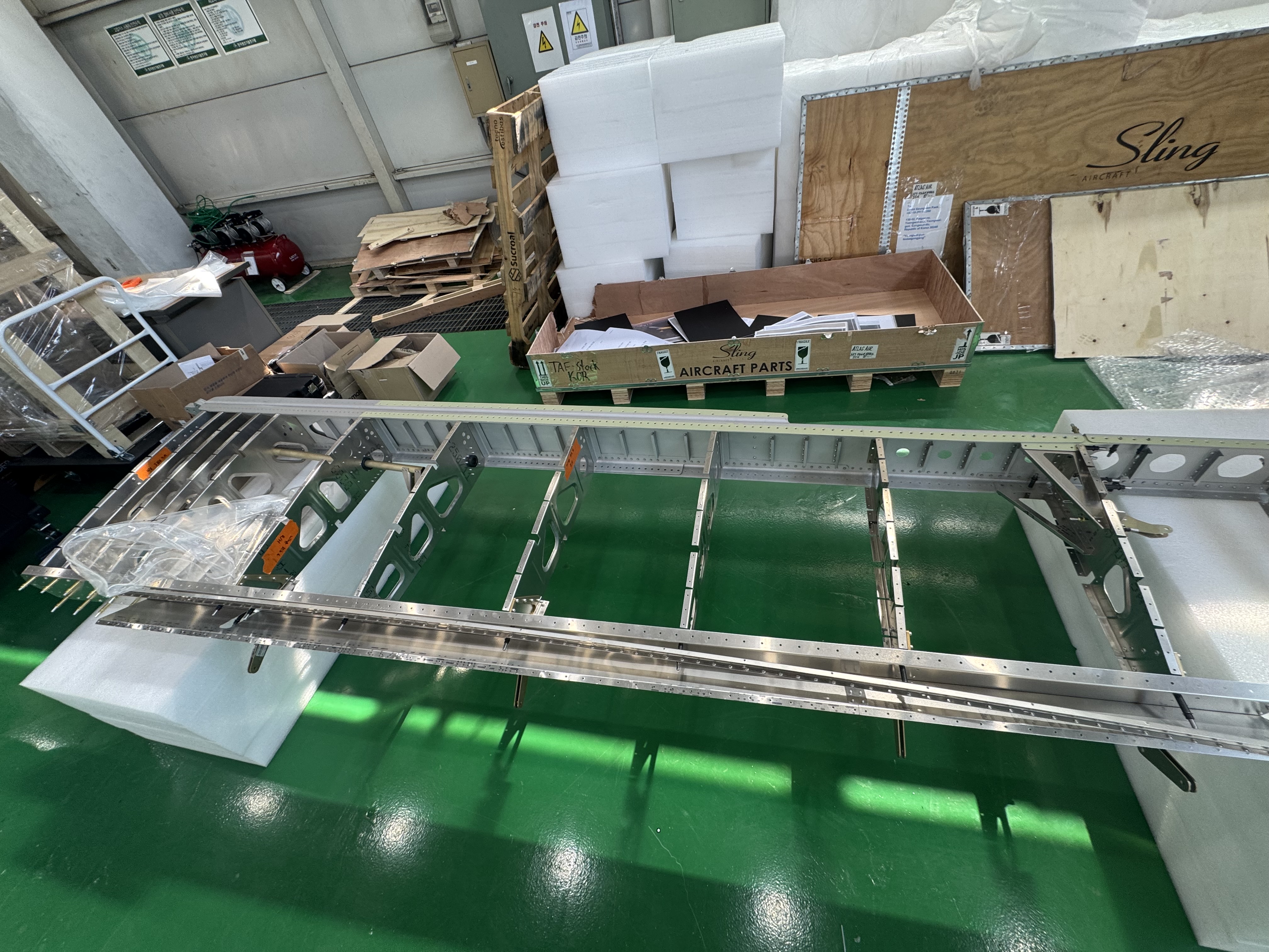
Figure 11. Assembly – phase 1.
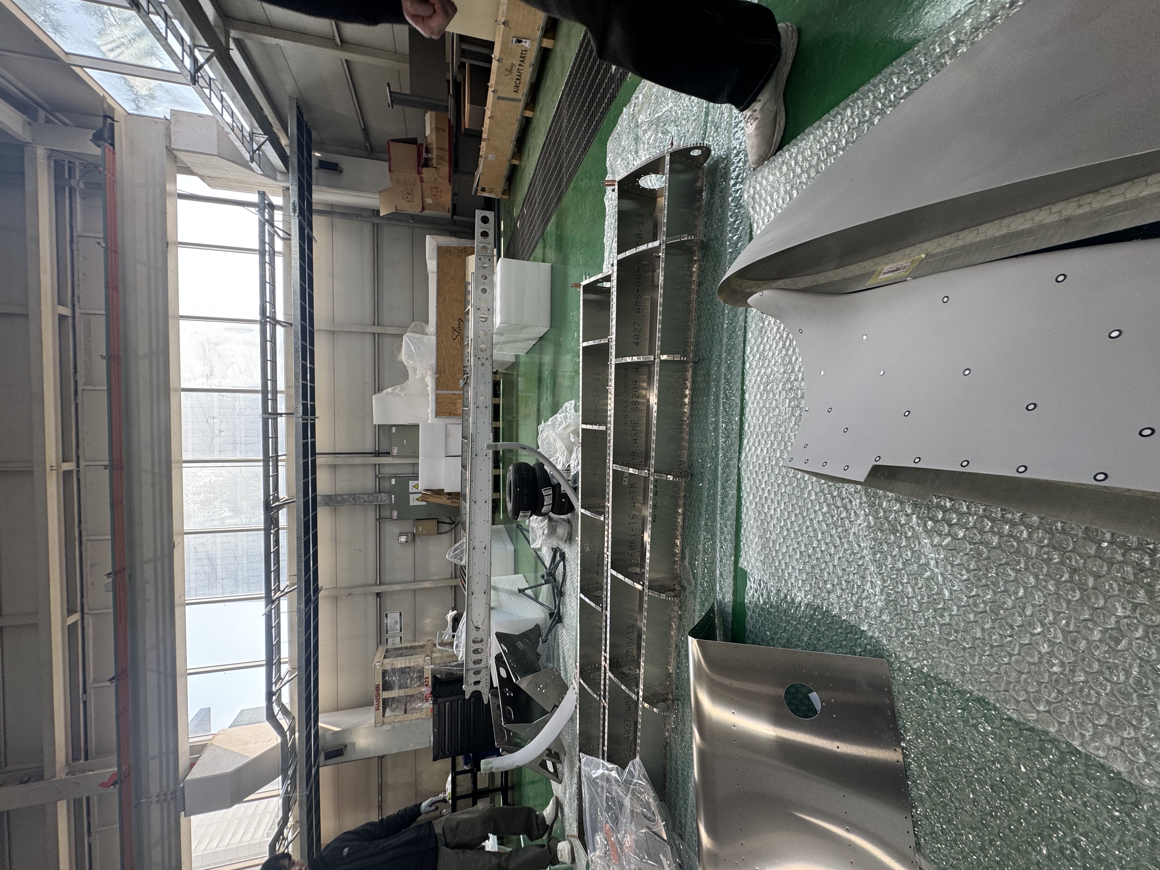
Figure 12. Assembly – phase 2.
6. Validation and Testing – Extended Dataset
System modeling aligned with certification structure
CG range validation using simulation and structural modeling
Fault scenarios for power transfer and control redundancy
EMC simulation and shielding concept validation
CFD testing for aerodynamic and lift interference margins
Physical integration review during ongoing system integration and airframe assembly under TC regulations
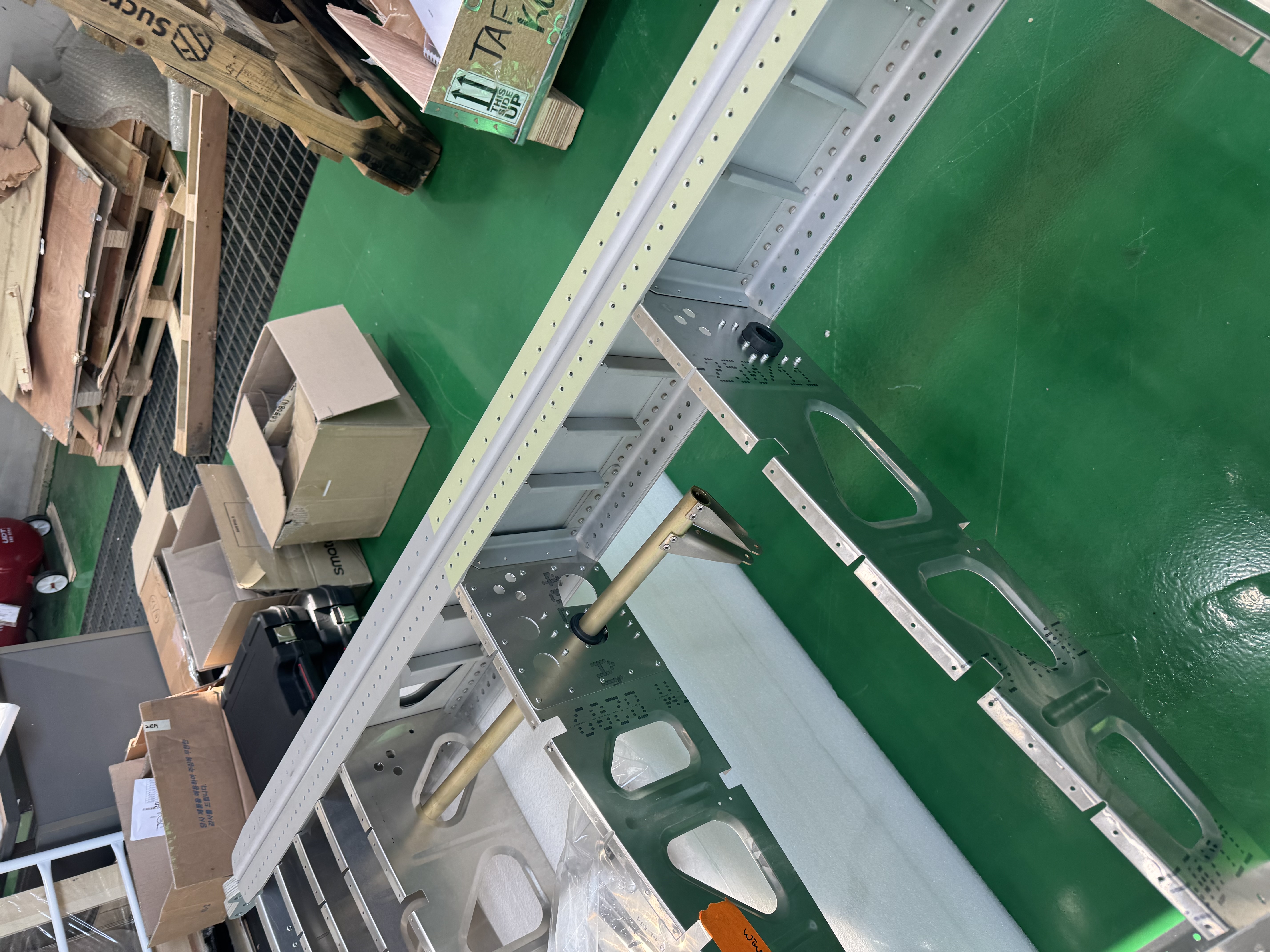
Figure 13. Assembly.
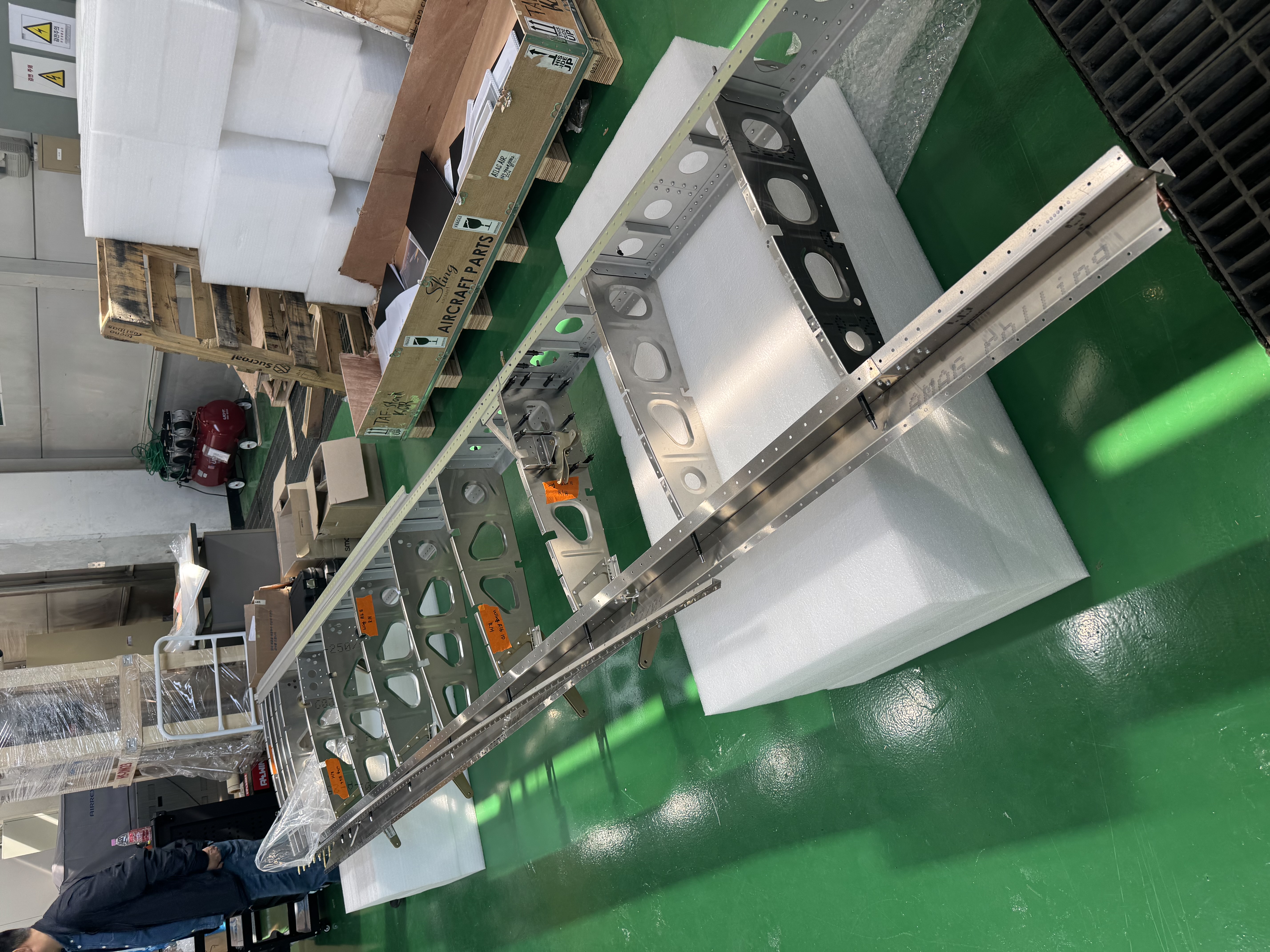
Figure 13. Assembly.

Figure 14.Assembly.
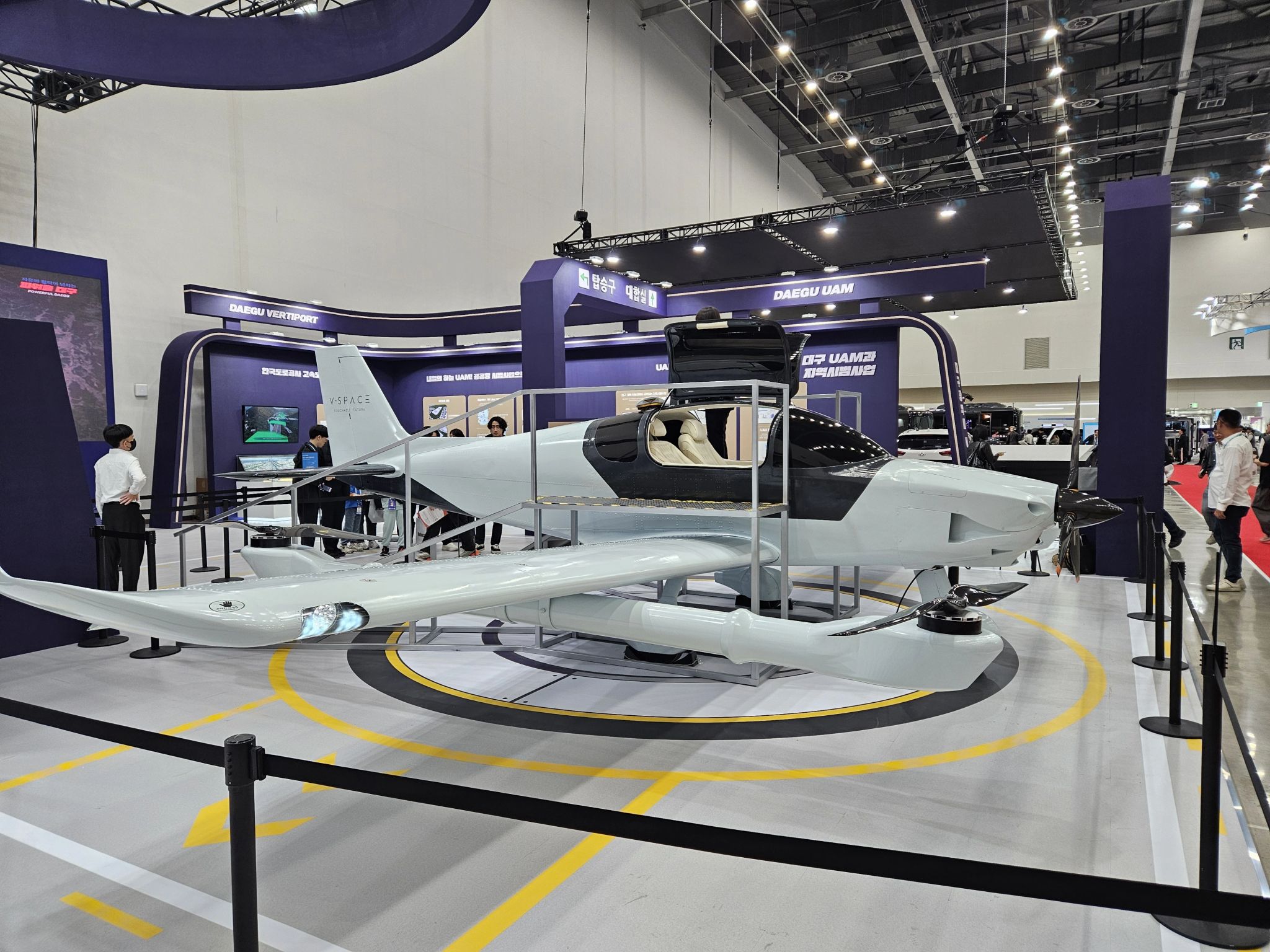
icture . UAM protype Built.